
The bin picking system, equipped with advanced robotics and vision technology, excels in unstructured environments by offering complex object recognition and path planning at the millimetre level.
Research Focus
| Object detection |
| 3D Pose Estimation |
| Path Planning |
Target
| Beneficial for the manufacturing assembly sector, particularly those handling bulk material, for example automotive and electronics industries As well as in waste management and recycling centres. |
Demonstrator Description
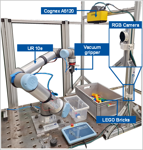
Bin picking demonstrator aims to sort the corresponding Lego parts for Lego products. The Lego product is chosen by the client randomly (see Figure 1).
Hardware
Figure 1 shows the Cognex A5120 3D camera system. It is mounted on top of the item bar, with its working space focused on the table. The Lego bricks stay in a cluttered and unstructured bin. The Robot arm Universal Robot UR10e grips Lego bricks with self-developed vacuum gripper and waits for RGB camera RealSense L515 colour detection to sort them in the small box.
Software Framework
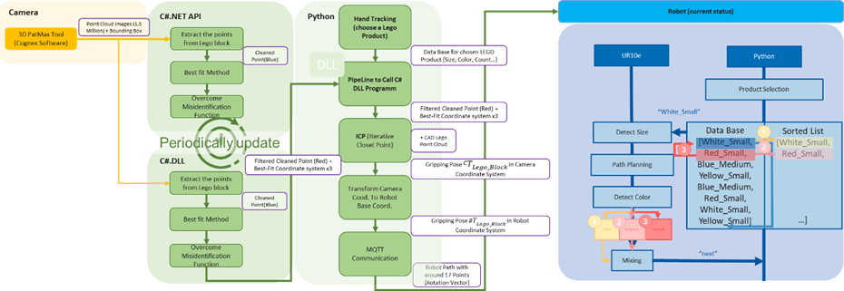
Figure 2 shows the software framework of Bin Picking use cases. On the left side the 3D Camera and the detection tool train and detect the objects. Output from camera are 1.5 Mio point clouds and the volume of interest (see Figure 2 Camera). C#.NET API interfaces with the camera software and visualizes the image processing results (see Figure 2 C#.NET API). In the development phase the C#.NET API makes the image processing to get the cleaned point clouds on the surface and detects the correct objects without misidentification. C#.DLL updates periodically with C#.NET API and outputs a DLL file und the image processing results to python (see Figure 2 C#.DLL). In the main program, a person selects a Lego product at the outset. C#.NET and C#.DLL detect the object and estimates the 3D gripping pose. Iterative Closest Point (ICP) matches the cleaned point cloud with CAD together to estimate more accurate 3D pose. The 3D pose, based on the camera coordinates system, transforms into robot coordinates system. The robot arm grips Lego bricks and waits for RGB camera colour detection to sort them in the small box using MQTT communication (see Figure 2 Python). The robot sorting strategy depends on the size and colour of Legos.
Vision Pro 9.7
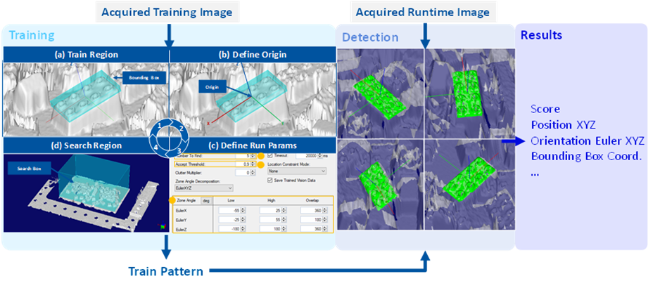
The Cognex A5120 camera is equipped with A5000 Viewer and Vision Pro 9.7 software. VisionPro software is an industry-leading PC-based image processing software. A5000 Viewer software configures the parameters of the 3D camera such as volume of interest and saves them to obtain a clear point-cloud representation. In this research project, we use readymade-software to train features from an industrial product based on a point-cloud representation of the product. Classical training features the Lego-Brick to circular knobs on the surface and different plain sides (see Figure 3).
C#NET API
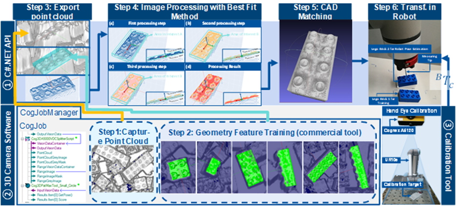
Figure 4 illustrates how the 3D camera software, and the calibration tool are used and which method in the application interface is developed because of this research. The C# .NET application programming interface (API) (see Figure 4 ①) was developed to make the point-cloud processing possible because vision pro does not support outputting point-clouds
Firstly, a 3D-Camera is used to capture a point-cloud image from the bin including its content (see Figure 4 Step 1). Hereafter, the point-cloud is processed with a commercial tool. Its purpose is to train geometrical features of the Lego-Brick to detect a single Lego-Brick in the point-cloud (see Figure 4 Step 2). However, the commercial tool simply outputs a bounding-box (8 corner points), therefore the 3D point-cloud and the bounding-box need to be matched to extract only the point-cloud belonging to one Lego-Brick (see Figure 4 Step 3).
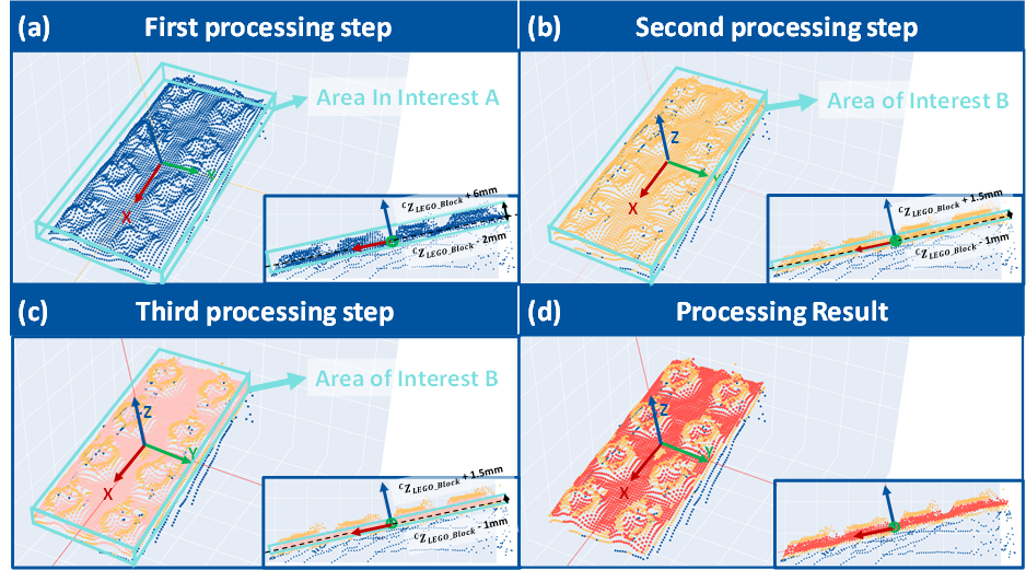
At this stage, the point-cloud for the Lego-Brick involves noise and knobs of the Lego-Brick, which need to be filtered. Hence, a best-fit-method is applied to process the resulting point-cloud of step 3 which determines the orientation of the Lego-Brick ‘s surface point-cloud (see Figure 4 Step 4, detail in Figure 5). The result is a denoised point-cloud without knobs (see Figure 4 Step 4-d).
The best-fit method aims to extract the necessary points of the current point-cloud. A point-cloud only describing the surface of the Lego-Brick without circular knobs and other noise is considered sufficient. Based on that a more accurate 3D gripping pose is estimated.
In the first step, a bounding box is set up that encompasses only the surface of the Lego-Brick, including the nodes. The length and width of the area of interest A are slightly larger than the actual length and width of the Lego-Brick itself (see Figure 5a). In the second step, the point-clouds representing the knobs are removed whereas the points representing the Lego-Bricks surface are preserved. The area of interest B corresponds to the actual size of the Lego-Brick surface (see Figure 5b). Repeating the second process increases accuracy (see Figure 5c). Figure 5d shows the result of the best-fit method.
C#NET DLL
Compared to C#.NET API, C#.NET DLL updates periodically. to make sure that the result shows correctly in GUI program and update the same concept in C#.NET DLL. It outputs the .dll file, Filtered Cleaned Point (Red in Figure 5) + Best-Fit Coordinate system in three different times.
Main Program (PYTHON)
At the beginning, the human chooses a product and sends the database of the product to the 3D Camera, which the C#.NET DLL is called to get the filtered point cloud (Red Figure 5) and the Best-Fit Coordinates System based on the 3D Camera coordinates system.
At this point only a denoised point-cloud of the targeted Lego-Brick exists. However, more features are necessary to determine the gripping point. Therefore, the Lego-Brick point-cloud is matched with the according CAD-model to increase the accuracy of the result (see Figure 4 Step 5).
Finally, a gripping pose is determined for the robot to grip the Lego-Brick. As many systems like the 3D camera, CAD-Model and Robot are involved in this process, the different coordinate systems need to be considered (see Figure 4 Step 6).
Robot Controller
The right side in Figure 2 shows an example of database with the first entry “White_Small”. The 3D camera detects the small size of the Lego-Bricks. After picking it, the robot moves in front of the RGB camera to detect the colour.
If the colour is “White”, the robot places the Lego-Brick in the sorting place and human helps to mix the Lego-Brick again and continuously sort the next Lego-Brick in the database.
If the colour is another colour e.g., “Red”, the system checks firstly if the Lego-Brick is required in the database, if it is required in the database, the robot places the Lego-Brick in the sorting place. But if it is not required in the database e.g., wrong colour or “None”, the robot throws the Lego-Brick on the table. The loop stops when all the Lego parts in the database are sorted.
Communication Protocols
Google MediaPipe
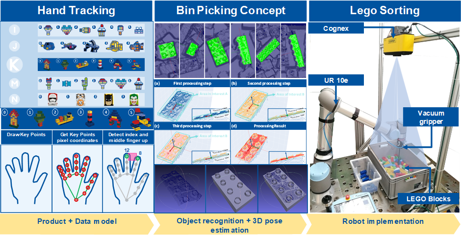
The primary function of Python’s main program is to invoke MediaPipe from Google for hand tracking and product selection within the Lego group (see Figure 6 Hand Tracking). According to the official google website, MediaPipe Solutions provides a suite of libraries and tools for you to quickly apply artificial intelligence (AI) and machine learning (ML) techniques in your applications. Once a Lego group is selected, the corresponding data model containing details such as size, colour, and account is transmitted to the 3D camera situated between the Python and C# pipeline. The 3D camera identifies the size of Lego bricks and predicts their 3D gripping pose based on the camera’s coordinate system. Subsequently, the 3D gripping pose is relayed back to Python’s main program (see Figure 6 Bin Picking Concept).
MQTT
The real-time communication between Python’s main program and the universal robot UR10e is with MQTT communication protocol established. According to the official website, MQTT protocol is designed as an extremely lightweight publish/subscribe messaging transport that is ideal for connecting remote devices with a small code footprint and minimal network bandwidth. The robot’s path is determined by the picking pose obtained from the 3D camera and the placement poses retrieved from a real-time json file. Within the MQTT communication, the system monitors messages related to colour detection from the RGB camera and the actual position from UR10e. This information is crucial for making decisions about whether to sort the Lego brick or discard it from the bin (see Figure 6 Robot implementation).
Scenario Description (Applications)
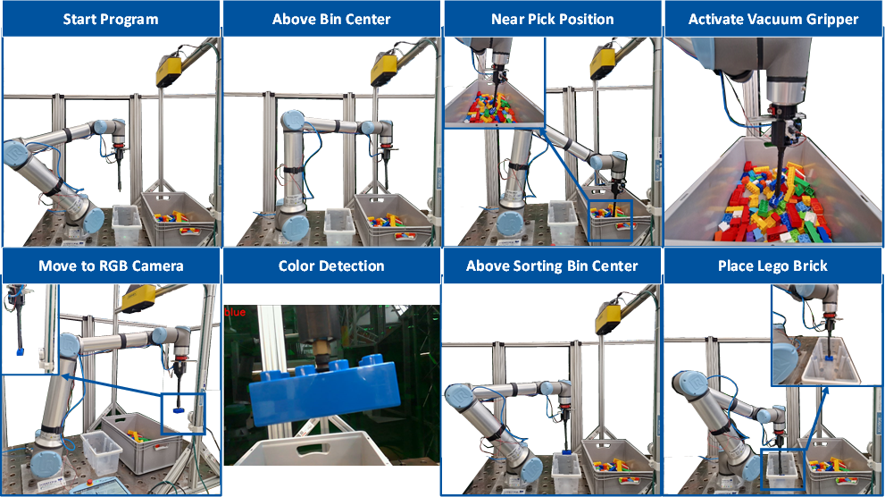
As shown in Figure 7, the robot arm moves to the Lego bricks detected by the 3D camera system and opens the vacuum gripper to grip them. Oriented perpendicular to the Lego-Brick surface, the robot moves near the Lego brick and activates the vacuum gripper a short distance above. To detect colour, the robot arm moves in front of the RGB camera as it grips the Lego brick. As a threading program, the robot activates the colour detection program. The RGB camera detects the colour of the Lego brick after several seconds and sends it back to the robot. If the size and colour satisfy the required data model, the robot arm sorts the Lego bricks into the small white box. If the colour is not satisfied, the robot moves out the Lego brick from the bin and sorts it for the next Lego brick.
List of Used Modules and Realized Applications
| Module Name | Description | Application |
| Object Detection | Based on 3D PatMax Tool (Cognex commercial tool). It can train a new object in one to two minutes. To solve the misidentification, C# program was developed with sampling (signal processing). | Bin Picking |
| 3D Pose Estimation | C# software, to estimate the precise 3D pose. The system uses objection detection module, best-fit method for image processing and matching with CAD point clouds using an iterative closest point method. | Bin Picking |
| Path Planning | The path is planned in MQTT communication protocol which depends on the pick position of 3D camera and the saved place position on the table. | Bin Picking |