
The assembly at DFKI Saarbrücken is an extension of the Remote Human-Human Collaboration Demonstrator. An operator uses the system (locally or remotely) to disassemble a battery pack. The robot should learn from the actions of the human operator and will at some point be able to carry out the required actions by itself.
The other assembly at DFKI Kaiserslautern is a battery use case which illustrates the process of assembling an AAA battery pack, followed by a failed visual (via AI-based object detection) quality check for battery leakages and a reassembly step inserting healthy batteries. Both assembly demonstrators can probably be combined at some later point.
Research focus
| Imitation Learning |
| Object Detection |
| Modular & skill-based production |
Target
| Saarbrucken – Interesting also for containment situations, i.e. actions that need to be carried out in protected areas like clean rooms in chip manufacturing. This demonstrator is co-financed by Intel. |
| Kaiserslautern – Interesting for the manufacturing sector, coping with modular and skill-based production. |
Demonstrator Description
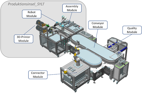
The demonstrator testbed shown in Figure 2 is a modular workstation called productionisland_KUBA used in this project to assemble, reassemble, and check for battery leakages of the battery pack shown in Figure 2. The productionisland consists of three production modules – the Connector Module, the Quality Control Module and the Conveyor Module, as well as a further productionisland_SYLT, which includes a 3D printer, a robot and a manual assembly module. Productionisland_KUBA is controlled via a multi-agent system (MAS) (see the Software section).
Important note: The hardware of this demonstrator is not built by RICAIP but is used as existing testbed in Kaiserslautern for the shared battery pack use case.
Hardware
Due to different independent modules on the demonstrator, we will describe each module in the following paragraphs.
The Conveyor Module is the highly flexible ACOPOStrak transport system (B&R) including multiple (currently five) shuttles. It connects the individual production modules for an optimized material flow. All other modules are mechanically interlocked at one of the physical gates of the transport system. Besides the mechanical interlocks Secure RFID sensors mounted on both sides (modules) allow a mutual identification. All other listed modules can be positioned freely at a certain gate at the transport system. The shuttles are requested as required and navigate independently to their destination. The transport system itself is a magnetic conveyor belt. This belt has a modular structure, whereby individual segments can be converted into a flexible design. Currently, all segments together build a big and a small circle. Controlled is the AcoposTrak by a B&R X20 system as programmable logic controller (PLC).
The Quality Control Module uses state-of-the-art AI-supported image processing to carry out a reliable quality inspection of the manufactured products. For the image capturing a Basler acA1440-73gc camera is used. The connector module consists of a 5G network, a robot arm and four storage yards. The robot arm by Pilz (PILZ manipulator PRBT 6) has the essential safety features of an industrial robot. It is used to feed components into and out of the productionisland_KUBA. A wireless hand-held control unit is used to control the robot and the production module. Modeled on a classic teach panel, it has a touch HMI, an emergency stop switch, an enabling device and an operating mode selector switch. The use of the PROFIsafe protocol for the signals of the safety devices ensures functional safety, despite radio transmission via 5G to the production module. For the 5G network two routers from PhoenixContact (Privnet 5G) create a tunnel between both network segments.
The Productionisland_SYLT is a modular module that was developed against the background of highly modular and flexibly reconfigurable production. It is being continuously expanded. The core concept is encapsulated units at different levels with embedded controls, which can be aggregated into more complex units. The module configuration consists of a central logistics module and four linked submodules with different production resources. The logistics module offers an articulated arm robot (UR5e) and a linear axis to ensure universal material transport across all peripheral modules. As submodules _SYLT has a 3D-printer (Prusa i3mk3s), a gripper attachment module to swap the gripper type between a parallel gripper as default and a vacuum suction gripper, and a manual assembly module. The focus here is on the interaction between man and machine. According to the vision of Production Level 4, humans remain an essential part of production, which should be emphasized here. Controlled is the productionisland_SYLT by a ctrlX device by Bosch Rexroth as main controller. The 3D printer uses a Raspberry-Pi as separate control device.
Software Framework
As Software Framework a Multi-Agent System (MAS) is used to control the hardware on a high level, manage production orders and monitor the execution of them. The current architecture of the Multi-Agent System[1] is displayed in Figure 3.
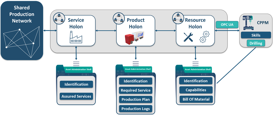
The MAS consists of three holons. A holon is an autonomous, intelligent, and cooperative building block of a manufacturing system for transformation, transportation, storing and / or validating information and physical objects [2]. The main difference towards an agent is that a holon implements the holonic concept proposed by Koestler[3]. This concept defines that a holon is a semi-autonomous sub-whole that is interconnected to other holons to form a whole. This interconnection enables holons to build quite flexibly hierarchical and heterarchical structures.
Coming back to the given architecture, we will see some examples for the hierarchical composition of holons and the advantage of the concept in comparison to an agent-based approach. The basic structure of our MAS follows the general idea of PROSA[4]. All holons use an own asset administration shell (AAS) type. AASs are an industry 4.0 related, vendor-independent technology for digital twins developed by the Plattform I4.0 [5]. The holons and the AAS complement one another. Holons are the active part of the digital twin, they load and store data from an AAS and process execution and planning tasks. In addition, the AAS is the passive part and contains the data. As framework to host and manage AASs, we use Eclipse BaSyX[6] based on the BaSys project. Following a more detailed description of the holons in our MAS.
The Service Holon displayed on the left side of Figure 3 manages and provides services of the factory to the connected world. For us, each productionisland can be connected to the outside world like other sights in RICAIP. This means that the productionisland_KUBA has one service holon, which manages these connections. The idea of using services comes from the capability-service-skill concept[7]. In this concept a skill represents a “description of the commercial aspects and means of provision of offered capabilities”. A Capability can be seen as an “implementation independent specification of a function […] to achieve an effect in the physical or virtual world”. Finally, a skill is the machine-specific implementation of a capability. Sticking to services in the service holon, one example of a service is the 3D-printing service, which offers the capability of producing customized products using a fused deposition modelling process. As already mentioned, the Service Holon represents the interface to the factory. For this reason, the Service Holon takes care of the Factory AAS. This AAS uses a unique identifier, a name and other general information to identify the productionisland. Furthermore, it contains a description of all assured services, the factory has to offer. Based on this service catalogue, other RICAIP members can request an offered service. Besides offering services, the Service Holon enables the MAS to process external tasks like ordering a specific product or executing a provided service. Furthermore, the Service Holon takes care of the disposition of external services, products or substitutes. In case of incoming production requests, the Service Holon processes these requests and requests the Product Holon to handle the request.
The Product Holon takes care of the production process and subdivides production tasks into different subtasks. In this context, the holonic approach takes effect. Each holon is responsible for one task and spawns for every subtask a Sub-Holon. Together, they display the production process in a tree-like manner. To handle these incoming tasks or derived subtasks, each holon triggers an internal execution at the Resource Holon or requests an external execution from the Service Holon. In the case of an internal execution, each Holon needs to check if the execution is feasible. Therefore, the Product Holon first matches the capabilities given by the resources to the desired capability to fulfil the (sub-)task. If both capabilities fit together, a feasibility check on the resources is triggered to simulate if a resource is able to perform the task under posed conditions (e.g., if the process can supply the desired product quality and evaluate estimated time, costs and consumption). After a successful feasibility check, the Product Holon spawns an AAS as Digital Twin for the product. The Product AAS contains information towards the product identification like a name and a unique identifier. If the AAS contains some subtasks which require an external execution, the Product AAS contains a description of all required external services to execute the subtask. After starting the production process, the Product Holon further controls the process by triggering production steps or monitoring the current production state. To monitor the execution process, the Product Holon updates the corresponding Product AAS by adding logging data to the production log. Both the Product Holon and product AAS together can serve as product lifecycle management tool during the production or recycling of the product. The AAS can then be used for further lifecycle phases like the creation of the product (e.g., storing and altering CAD files) or the utilization of the product.
The Resource Holon takes care of the management of production modules. Our Resource Holon consists of an arbitrary number of Holons, where we distinguish between a Resource Holon of type Island and Module. The former is used to emphasize the existence of Sub-Holons, while the latter type is used to highlight the module as smallest agent that won’t be further partitioned into smaller agents. The Island Resource Holon of _KUBA is responsible for lifecycle management and coordination of other holons, i.e., to add or remove a module from the demonstrator, a module agent needs to be (un-)registered at the Island Holon. Besides that, the Island Holon receives production requests from the Product Holon and forces or requests the production from the Module Holons, which are able to handle the request. The productionisland_KUBA holon uses for these purposes an own Island Resource AAS. This AAS provides information on the topology of the Island Resource Holon and how to connect to other sub-holons.
On the other hand, Module Holons schedule and perform the concrete tasks on their connected resources. In case of a production request, each Module Holon can create a bid in the range between 0 and 1. The bid determines the desire to perform the job. This bid is part of the bidding protocol[8]. Connected to the Resource Holon a Resource AAS contains all offered capabilities and parametrized skills of the module. These capabilities and skills are used during the planning phase to determine of the resource is capable of executing a production request.
Besides the MAS, our demonstrator uses a bunch of different technologies to administer the low-level control layer on each module. Since we won’t work with them in detail in this project, we won’t present them here in detail. Besides classic control software of the respective hardware like ctrlX works or B&R Automation Studio, we use ROS to control our one arm robots. Furthermore, each module has an own human control interface to enable an operator to control the module without accessing the MAS.
Communication Protocols
As communication protocol we use different technologies in our system. For the communication to the shared production network, the Service Holon communicates with other sights via an asynchronous event-based communication based on the industry 4.0 language. This implements VDI/VDE 2193 [[9], [10]] as chosen communication standard. Currently supported technologies are publish/ subscribe communication protocols, namely MQTT and Apache Kafka. The same communication type is also used between different holons in the Multi-Agent System. As communication technology Apache Kafka is used. Apache Kafka is an open-source distributed event streaming platform used for high-performance data pipelines, streaming analytics, and data integration.
For the communication with the PLC layer the technology OPC UA is used. OPC UA is a cross-platform, open-source, IEC62541 standard for data exchange from sensors to cloud applications developed by the OPC Foundation. Devices on the PLC layer use multiple communication (physical and non-physical) technologies. Among them are PROFINET, Ethernet, Modbus, and Powerlink.
Scenario Description: Battery Pack Assembly & Disassembly
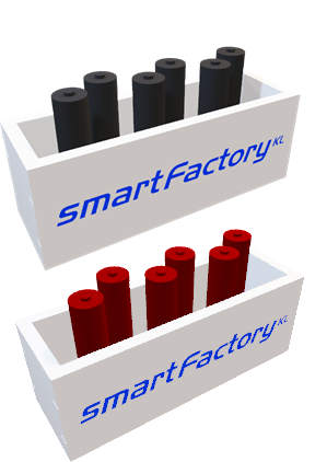
This scenario is about the assembly and disassembly of a battery pack. The idea of this process is to show a cooperation of multiple sights with adaptive process driving. For this scenario a simplified battery model for 3D printed triple-A battery, and a battery case together with an inlet to insert the batteries are designed. In comparison to other battery pack use cases no screws are used, and thus screwing is not an included activity in our process. The battery models currently have two different colours: Red and Black. A red battery indicates a battery with a battery leakage. Black batteries represent correct batteries with no faults and leakages. The colour of the battery is used for the camera recognition process on the quality control module. Until now, this use case is in the prototypic state and will be expanded in the future. Following, we will describe the current process to show this scenario. The process differs to the prototypical process shown in the video in the first section.
Let us first start with the initial state of the process. We assume that a human already placed enough red and black batteries in a storage at the manual assembly station at productionisland_SYLT and that a battery chassis consisting of a 3D-printed battery case and an inlet in the battery case is located at the connector module. When starting the process over the module, the following skills are executed:
- Load battery chassis to the AcoposTrak – Connector Module
- Transport battery chassis to Productionisland_SYLT – AcoposTrak
- Transport battery chassis to the manual assembly station – Productionisland_SYLT
- Assemble black and at least one red battery into the battery chassis – Assembly Station
- Transport battery pack to the AcoposTrak – Productionisland_SYLT
- Transport battery pack to the Quality Control Module – AcoposTrak
- Check the quality of the battery pack (in this case as insufficient, due to a red battery) – Quality Control Module
- Transport battery pack to the productionisland_SYLT – AcoposTrak
- Transport battery pack to the manual assembly station – Productionisland_SYLT
- Reassemble battery pack and replace all red batteries with black batteries – Assembly Station
- Transport battery pack to the Acopostrak – Productionisland_SYLT
- Transport battery pack to the Quality Control Module – AcoposTrak
- Check the quality of the battery pack (in this case as sufficient) – Quality Control Module
- Transport the battery pack to the connector module – AcoposTrak
- Load battery pack to the output storage – Connector Module
Considering the bold marked activities in this process, the main idea is to show parts of the production process combined with a dedicated control and/ or recycling step in one process. The first assembly step represents a production step of the battery pack, although this time already a faulty (red) battery is inserted in the battery case which might stand for an error during production or a battery leakage originating from the utilization of the product. The following quality check detects the faulty battery based on an own AI based object detection algorithm implemented in YOLOv5. As a result of the object detection, the batteries are classified as missing, incorrect (red batteries) or correct (black batteries). If faulty or missing batteries are detected which might happen during production or a recycling phase, the batteries are reassembled at the assembly station. Reassembly in this case means to replace all faulty or missing batteries with new working batteries. At the end, the quality of the battery pack is checked once more to ensure the correctness of all working batteries.
List of used Modules and Realized Applications
| Module Name | Description | Application |
| MAS | Based on the developed MAS mainly in other projects (MAS4AI and SmartMA-X), the MAS is improved on different levels to support the battery pack use case as further use case besides the existing truck use case. | Battery Pack Assembly and Disassembly |
[1] A. T. Bernhard u. a., „I4.0 Holonic Multi-Agent Testbed Enabling Shared Production “, in Artificial Intelligence in Manufacturing, in Artificial Intelligence in Manufacturing., Springer Nature, 2024.
[2] E. H. van Leeuwen und D. Norrie, „Holons and holarchies “, Manufacturing Engineer, Bd. 76, Nr. 2, S. 86–88, Apr. 1997, doi: 10.1049/me:19970203.
[3] A. Koestler, The ghost in the machine. in The ghost in the machine. Oxford, England: Macmillan, 1968, S. xvi, 384.
[4] H. Van Brussel, J. Wyns, P. Valckenaers, L. Bongaerts, und P. Peeters, „Reference architecture for holonic manufacturing systems: PROSA“, Computers in Industry, Bd. 37, Nr. 3, S. 255–274, Nov. 1998, doi: 10.1016/S0166-3615(98)00102-X.
[5] Industrial Digital Twin Association, „Specification of the Asset Administration Shell Part 1: Metamodel“. 2023. [Online]. Verfügbar unter: https://industrialdigitaltwin.org/wp-content/uploads/2023/06/IDTA-01001-3-0_SpecificationAssetAdministrationShell_Part1_Metamodel.pdf
[6] „BaSyx – Eclipsepedia“. Zugegriffen: 22. Dezember 2023. [Online]. Verfügbar unter: https://wiki.eclipse.org/BaSyx
[7] „Information Model for Capabilities, Skills & Services“. Zugegriffen: 22. Dezember 2023. [Online]. Verfügbar unter: https://www.plattform-i40.de/IP/Redaktion/EN/Downloads/Publikation/CapabilitiesSkillsServices.html
[8] S. Jungbluth, N. Gafur, J. Popper, V. Yfantis, und M. Ruskowski, „Reinforcement Learning-based Scheduling of a Job-Shop Process with Distributedly Controlled Robotic Manipulators for Transport Operations“, IFAC-PapersOnLine, Bd. 55, Nr. 2, S. 156–162, Jan. 2022, doi: 10.1016/j.ifacol.2022.04.186.
[9]VDI/VDE 2193 Blatt 1 – Sprache für I4.0-Komponenten – Struktur von Nachrichten. 2020. Zugegriffen: 5. Dezember 2023. [Online]. Verfügbar unter: https://www.vdi.de/richtlinien/details/vdivde-2193-blatt-1-sprache-fuer-i40-komponenten-struktur-von-nachrichten
[10]VDI/VDE 2193 Blatt 2 – Sprache für I4.0-Komponenten – Interaktionsprotokoll für Ausschreibungsverfahren. 2020. Zugegriffen: 5. Dezember 2023. [Online]. Verfügbar unter: https://www.vdi.de/richtlinien/details/vdivde-2193-blatt-2-sprache-fuer-i40-komponenten-interaktionsprotokoll-fuer-ausschreibungsverfahren