
The Multi Agent System facilitates coordination among various demonstrators by allowing autonomous agents with multiple tasks, such as controlling production modules or sharing information and status updates.
The demonstrators feature Raspberry Pi assembly and bin picking, alongside the MiR robot, which automates material transportation.
Research Focus
| Multi Agent System (MAS) |
Target
| Interesting for the Manufacturing sector to improve assembly line efficiency, distributed production and component logistics. |
Demonstrator Description
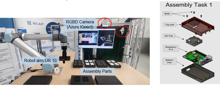
The station resembles a manual workstation, where a human is supposed to assemble a Raspberry Pi (RPi) circuit board into a 3D printed casing.
Hardware
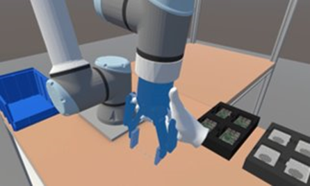
The station consists of a Universal Robot UR10e collaborative robotic arm with a ROBOTIQ 2F-140 Adaptive Gripper. Additionally, there are three RGBD Cameras (Microsoft Azure Kinect) in charge of object detection, intention recognition and point cloud generation. Three different computers equipped with graphics cards in charge of running the demonstrator and all its processes. A virtual reality headset (Meta Quest2) that can be used for the remote or local collaborative assembly process. The assembly parts used to demonstrate Raspberry Pi assembly are upper cases, lower cases, fans and RPi circuit boards (see also Figure 1), they are organized in foam containers (inlay bins).
For demonstration purposes, there is also a large, mobile TV screen, e.g., to show the 3D view of an MR (Mixed Realty) headset etc.
Currently, we provide two demonstrators using this station: local collaborative assembly and Mixed Reality (MR) based remote assistance.
Software Framework
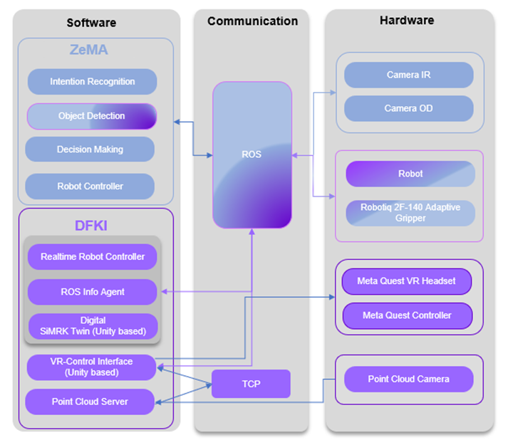
Figure 2 shows the general implementation pipeline of the demonstrator station, which was developed by ZeMA and DFKI. On the right side, the used hardware is shown, the left side shows the different software modules, developed by ZeMA or DFKI, and the middle represents the communication platform that is used to connect the different hard- and software components.
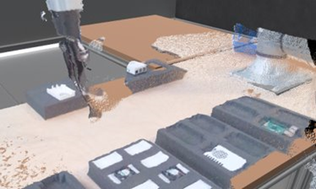
As stated above, the cameras are Azure Kinect RGBD cameras. Camera IR is used for the Intention Recognition (IR) and is slightly angled towards the worker. Camera OD is for Object Detection (OD) and is mounted above the tabletop, point straight downwards. The Point Cloud Camera is used to stream 3D data about the tabletop of the workstation, and is mounted to the side of the workbench, with an angle that gives a good overview over the tabletop.
A Meta Quest 2 Virtual Reality Headset with its associated controllers is used for the second scenario.
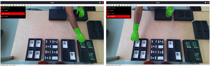
Itention Recognition
To evaluate the actions of the human, hands are used as the base feature. For which a model based on You only look at the coefficients (YOLACT) established on real-time instance segmentation is trained on a custom hand dataset.
YOLACT is a simple, fully convolutional model for real-time instance segmentation. It uses ResNet-101 with FPN (Feature Pyramid Networks) that helps in creating pyramids of feature maps of high-resolution images rather than the Conventional Pyramid of Images approach, therefore reducing the time and requirements of computational capabilities. It balances both speed and performance.
The dataset consists of over a 1000 high resolution images containing hands varying in size and color in the assembly Environment. Each instance of the hand in every image was labelled with polygonal annotations using LabelMe tool.
These features are later combined with the depth values from Azure Kinect camera and passed on to the next part of the inference module where a temporal model based on Long-Short Term Memory (LSTM) based is trained.
LSTM networks are a type of recurrent neural network (RNN) capable of learning order dependence in sequence prediction problems.
The based LSTM model is trained offline on a sequence of images whereas the inference is evaluated online on a real-time video. The output is categorized into the type of bin the hand is headed towards i.e. [bottom, raspi, fan, top].
The intention recognition model achieves an accuracy of 98.5% (see results in Figure 3)
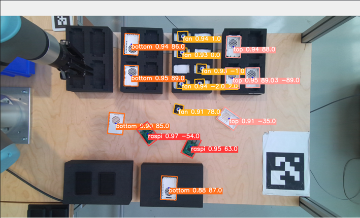
Object detection
The robot needs to be aware of the product it is assembling as much as it should be of the human state. This is accomplished by the second module of perception, where not only the product parts are detected inside the bins but also the state of the product itself is detected as well.
Object detection pipeline is based on recent release of the You Only Look Once (YOLO) family models YOLOv5 with original hyperparameters, to exploit transfer learning.
YOLO is a popular object detection model known for its speed and accuracy.It deals with localizing a region of interest within an image and classifying this region like a typical image classifier. One image can include several regions of interest pointing to different objects.
To supervise the object detection model learning, a rotated bounding box annotation from LabelMe tool is used, by drawing a box around each object and labelling each box with the specified object class.
The dataset consists of over 584 high resolution images. The model was trained on 384 images to identify 7 classes (raspi, bottom, fan, top, bottom-raspi, top-fan, case), tested on 100 images and validated it on 100 images. The model is trained offline on a sequence of images whereas the inference is performed online on a real-time video by receiving images from Kinect camera.
The object detection model achieves a Mean average precision equal to 0.93 (see results in Figure 4).
Decision Making
A task planner based on Q-Learning was implemented to select the best possible action for the robot agent based on the action of the human.
The approach follows basic Q-Learning, where the expected rewards for an action at a given state are estimated. Each state-action pair is assigned a Q-value. A higher Q-value indicates desired action whereas a low Q-value would indicate that the action is not useful. A table, also known as the Q-Table, is updated with the new Q-values every time an action is chosen over the course of the entire process. To ensure that the agent does not always choose the action related to the highest Q-Value, an epsilon-greedy functionality is enforced. This forces the agent to select random action with a certain probability to keep a balance between exploration and exploitation. The episode ends after all the parts are utilized and a final reward is given depending on the outcome. If the assembly was successful a reward of 1 is given and if the product assembly was not successful, a reward of -10 is given.
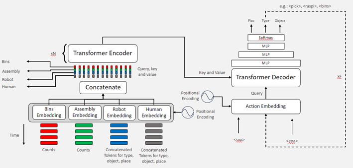
Due to results limitations of Q-Learning, a new transformer architecture is based on mechanism “self-attention” is implemented (see Figure 5).
Robot Controller
The robot controller pipeline consists of the controllers for the robot as well as the gripper. It is based on MoveIt which is an open-source ROS software for manipulation of robots. It offers features such as motion planning to generate high degree of freedom trajectories in an environment, manipulation options to analyse and interact with the environment, inverse kinematics solver to solve for joint positions for a given pose, 3D perception to connect to depth sensors for generating point clouds, and also collision checking to avoid obstacles in an environmental setting.
VR – Control Interface
The VR interface for the robot control was developed using Unity and the Mixed Reality Toolkit, which enables the implementation of VR-interaction and provides compatibility for most of the state-of-the-art VR-glasses. For the realistic representation of the UR10e, we imported the 3D model from its URDF description using ROS Sharp. To make the 3D model of the robot manipulable in VR, we use an implementation of the Bio IK algorithm. It provides inverse kinematics that supports constraints for one or more rotation axes of individual joints and allows the definition of multiple targets for multiple joints simultaneously, enabling multi-handed manipulation of the robotic arm (see Figure 57). With the resulting motion generation, we were able to replicate a natural and intuitive control of the real robot, where one hand of the user takes the role of guiding the robot’s end-effector (gripper) while the other hand can be used for stabilization, e.g. to fix joints in place. To make the robot-control safer, i.e. to avoid exceeding the joint limits, which would trigger an emergency stop on the real robot, a visualization of the corresponding joint limits in terms of an angular display with continuous colour gradient has been implemented which becomes visible when limits are approached (see Figure 59). Furthermore, the control interface is enhanced by incorporating stepwise and continuous gripper movement commands. These commands are executed through inputs from the VR-controller, offering precise and flexible control of the robot’s gripping mechanism. The generated motions of the virtual robot are transferred to the real counterpart using the real-time controller explained in the next section. To give the user an impression of what is happening around the real robot side, a connection to the Point cloud server is established and the current colour and depth images are tapped. By re-projecting the depth data, a point cloud is created and visualized in the virtual world (see Fig. 7)
Realtime Robot Controller
A robot controller was implemented so that movements on the virtual robot are accurately replicated on the real robot with low latency. The first iteration of the Realtime Robot Controller was a low-level controller implemented using the ROS Melodic controllers’ package, specifically, using a position controller. The current iteration uses the default Noetic implementation of a joint trajectory controller from the same package, albeit with some minor custom changes. This newer controller is more stable and with less overhead. It is possible to select the controlling frequency of the controller to match the sampling rate on the VR application.
MoveIt Planner
A client that uses the MoveIt python API was implemented. It allows the execution of cartesian, and joint space trajectories based on the current pose and a target pose. This client is used a base by a program that implements complex actions like pick and place, push, polish and hold, being commanded from the VR application.
Point Cloud Server:
A simple console application that captures the depth and color images of the Azure Kinect camera. Clients can connect to this application via TCP to access the current camera images and reconstruct a point cloud of the environment using the depth data. The image data is compressed using the zLib library to save bandwidth.
ROS Info Agent
An agent that quickly provides information about the current state of the robot was built. This is a REACT type agent and it was implemented using the Langchain framework. It can be driven by the GPT family of LLMs from OpenAI but also by OSS models like Llama. The agent can answer questions about the robot’s status, state, velocity, effort, the state of the program currently being executed, the state of the controller, but many others could be provided. This agent via RAG has information about general information about the UR family of robots given that a vector database was built around their technical documentation.
Visual Digital Twin (SiMRK)
SiMRK is a robotics simulation and visualization framework, developed in Unity. It enables the creation of detailed robot simulations that produce data streams for external application use. The tool not only simulates robotic operations but also allows the virtual robots to be configured so they receive data streams from real robots. Such a feature is particularly beneficial for monitoring real-time states, providing a comprehensive visual representation of the robot’s status and activities.
Communication Platform
ROS
The communication between software and hardware blocks is mainly established through Robot Operating System (ROS). According to the official wiki, ROS is an open-source, meta-operating system for robots. It provides the services you would expect from an operating system, including hardware abstraction, low-level device control, implementation of commonly used functionality, message-passing between processes, and package management. It also provides tools and libraries for obtaining, building, writing, and running code across multiple computers.
TCP
The Transmission Control Protocol (TCP) is a basic communication protocol in the Internet Protocol stack that enables reliable, orderly and error-free data exchange between network devices. It is used for applications where data integrity and reliability are of critical importance, such as when accessing websites, sending emails and transferring files. TCP achieves this through features such as sequencing data packets, acknowledging receipt and resending packets in the event of data loss, making it a key component of reliable data transmission on the Internet.
Scenario Description (Applications)
Scenario 1 – Raspberry Pi Assembly: Local Collaborative Assembly
The use case consists of an assembly task where a Human-Robot Collaboration (HRC) capable robot, the Universal Robot™ UR10e, is used to assist the human in completing the task. The robot agent needs to infer subsequent goals of the human by predicting their intentions and in turn perform either assembly steps or palletizing the assembly if it was successfully assembled.
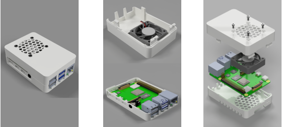
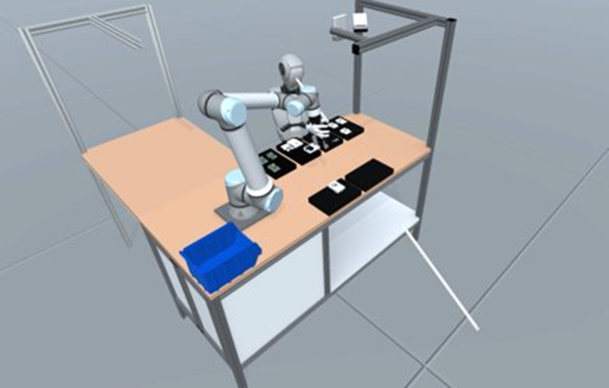
Figure 9 shows two different sub-assemblies, a pair of top part-fan and a pair of bottom part Raspberry Pi 4. The process can be carried out in various orders, one of the possible ways to complete the assembly is where the human first takes the bottom part of the case, subsequently the robot predicts the human action and grabs the Raspberry Pi from the bins and places it on the bottom part. In the next step the human goes on to pick up the fan and robot grabs the top part. The top part and the fan are then bolted together by the human. Once the two sub-assemblies are completed, the human again puts both together to close the assembly.
Data Flow
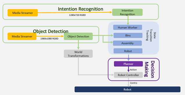
Figure 10 shows that the entire system is built around 3 major modules, prediction of the human action by detecting hands as the base feature of importance (Intention Recognition), keeping track of the bin state by detecting the products inside the bins (Object Detection) and lastly planning the task allocation for the robot to complete the assembly process successfully (Decision Making).
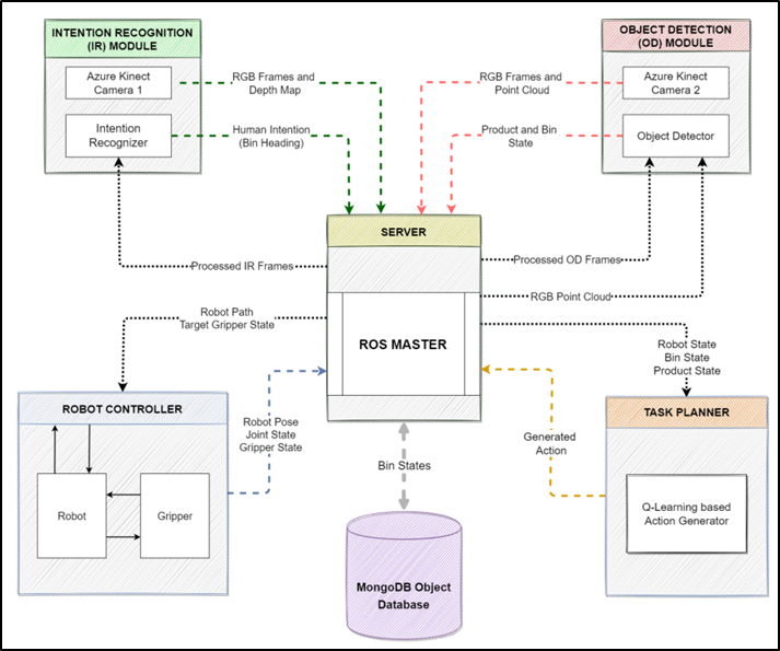
All the software modules were integrated together using ROS. Figure 11 shows the system architecture. There is a total of four ROS Nodes: intention recognition, object detection, robot controller and task planner, running together and are connected to ROS Master. The object detection node localizes the objects in the environment and publishes a custom ROS message that is an array of all the detected objects with their [X, Y, Z] coordinates. This message is subscribed to the task planner node which in turn updates the database about the current state of the bins and the assembly area. The intention recognition node publishes a string-based message which contains the label name of the bin the human is heading towards. This is also consumed by the task planner to generate a new action based on the human input and publish the generated action. The action is then subscribed to by the robot planner to generate a path for the robot.
Scenario 2 – Raspberry Pi Assembly: Remotely Assisted Assembly
This scenario showcases a collaborative assembly process for a Raspberry Pi 4 using advanced robotics and virtual reality (VR) technology. It involves a physical setup with the Raspberry Pi parts placed in a container on a workbench alongside a UR10e collaborative robot (cobot). The assembly is conducted by two human workers: one at the robot site assembling parts and the other, a VR-operator, controlling the robot remotely via a digital 3D representation using VR glasses and controllers. The system utilizes two Microsoft Azure Kinect RGBD camera modules. One camera identifies and transmits the parts’ positions, while the other provides a 3D view of the environment, helping the VR-operator understand the workspace, including obstacles and the co-worker’s actions. The VR-operator’s commands are transmitted to the robot using a ROS-based real-time controller, mirroring actions configured in the virtual environment. A monitoring component, part of the SiMRK4.0 platform, offers real-time rendering of the collaborative scenario, integrating data from various sources including the VR-operator and the robot.
In this use case, the UR10e robot is not acting autonomously, but is remote controlled via a VR headset by a worker who can be located at a different manufacturing site, e.g. the robot is located in Saarbrücken, and the remote operator is located in Prague (see Figure 12). The basic idea of this demonstration is to provide the remote operator with a VR 3D-representation of the workbench in Saarbrücken, including a 3D-model of the UR10e itself. The remote worker can manipulate the pose of the 3D robot representation using their “virtual hands”, like they would adjust the pose of a real robot by manually moving a joint in the desired position while the robot is free-drive mode. For example, they might grasp the end-effector and move it to a new position, and the robot will automatically adjust all other joints in order to be able to reach the desired end-position. Any such movement of the 3D representation of the robot will be synced back to the real robot and vice versa, i.e. any movement of the real robot will result in the same movement carried out in the VR representation. Additionally, the VR user can interact with the robot using natural language commands. For example, they might say, “Pick up the raspberry Pi.” This voice command is evaluated using Azure Services, generating actions that the robot then executes. Moreover, through the ChatGPT API, naturally spoken responses are generated, enabling a dialogue with the system.
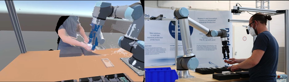
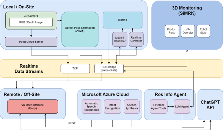
Figure 13 provides an overview of the overall architecture of the remotely assisted assembly scenario and divides the entire system into individual subsystems that can run physically separated and communicate with each other via a real-time data stream. The “Local / On-Site” system consists of the workstation including the UR10e robot and two Azure Kinect cameras that capture information about the physical environment. One camera is used by the Point Cloud Server, which transmits the scenes depth and colour information to the VR User interface via TCP. The Object Pose Estimation module uses the stream of the second camera and tries to detect and estimate poses of pretrained objects, which then can be visualized in the VR User Interface as well. The subsystem labelled with “Remote / Off-Site” consists of the VR User Interface which runs on a Meta Quest 2 VR Headset connected to a VR-capable desktop PC either via cable or wi-fi.
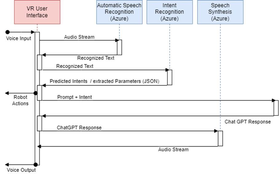
We use three different cloud services from Microsoft Azure to enable interaction with the system in natural language. These include speech recognition to convert spoken language into text, a specially trained language model that analyses the spoken text and recognizes the user’s intention, and a service that converts the system’s output into natural language. The system’s output is generated using the ChatGPT API. Based on the recognized intentions of the user, actions that can be executed by the robot are derived and forwarded to it.
Currently the speech model supports the recognition of pick and place intents as well as requests to the ROS info agent, which allows asking questions to the system about the current state and general information about the robot. Figure 14 shows the sequence of voice interaction from a verbal input to the execution of the action on the robot to the response of the system in natural language.
We use SimRK to visualize all data streams provided by the individual systems. This allows us to monitor the work between humans and remote-controlled robots in terms of error prevention or to analyse them in the context of studies. The monitoring of an assembly task is shown in Figure 15.
List of Used Modules and Realized Applications
| Module Name | Description | Application |
| Object Detection | Based on YOLOV5, the video stream of an RGB camera is analysed and the detected objects are classified. | Local Collaborative Assembly Remote Collaborative Assembly |
| Intention Recognition | Based on YOLACT and Long-Short Term Memory, the video stream of an RGB camera is analysed and the intention of human is defined. | Local Collaborative Assembly |
| Decision Making | Based on Q-learning, the action of the robot is defined based on environment state. | Local Collaborative Assembly |
| Real-time joint controller | Noetic based Low latency, variable control frequency controller suitable for Remote Collaborative Assembly. | Local Collaborative Assembly Remote Collaborative Assembly |
| MoveIt-planner | Planner for cartesian and joint space trajectories. Used a base for complex tasks like polishing or pushing. | Local Collaborative Assembly Remote Collaborative Assembly |
| VR – Control Interface | A VR control interface for robot manipulation including a realistic 3D representation, inverse kinematics, natural speech interaction, joint limit visualizations, and point cloud visualizations for intuitive and safe remote operation of a robotic arm. | Remote Collaborative Assembly |
| Point Cloud Server | A console app that captures and compresses colour and depth images and distributes the data to connected client applications | Remote Collaborative Assembly. |
| Visual Digital Twin (SiMRK) | A Unity-based simulation tool that can both generate and receive data streams to simulate and monitor robotic states for external applications. | Remote Collaborative Assembly. |
| ROS LLM info agent | LLM based REACT agent that solves questions about current state and general information about the robot using tools like RAG | Local Collaborative Assembly Remote Collaborative Assembly |