
Demonstrator description
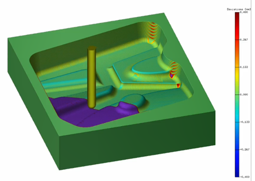
Complex shaped parts have complex surface errors after machining. These errors can be checked using virtual machining models. The virtual machining model produces group of data, which can be used for production validation. Main advantage is, that the surface errors are known from the virtual model before a real machining and the complex machining process can be correctly tuned. During the real machining process data are recorded and used for future validation algorithm and inspection purposes. The demonstrator shows distributed production, because tuning the machining process before real machining play an important role in digitalization and show how can be the machine tool setting be distributed to virtual simulation. After-machining validation is used to prove the final result to the customer in an understandable and clear way.
Hardware
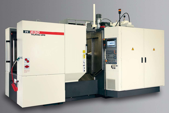
For this use-case machine tool manufactured by TAJMAC-ZPS in version H630 is used (Fig. 3). This machine is a horizontal milling centre equipped with pallet changer with two pallets and with tool magazine with automatic tool changing. The machine is determined to a productive complex machining of moulds, dies and components of flat or box shapes from steel, grey cast iron and soft metal alloys clamped on the operating pallet. It enables to perform the milling operations in three mutually perpendicular coordinate axes (X, Y, Z). The rotary table (B-axis) enables the machining from more sides. The functions of machine are operated by CNC operation system SINUMERIK 840D sl (software cnc version 4.94.) which enables machining of spatially complicated shapes when the tool follows the path created as an output from 3D CAD program. This machine is used as an experimental machine for use-case to show the whole workflow of virtual machining.
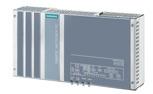
The edge computing is used for machining process digitalization via data mining. For this purpose Industrial PC SIMATIC IPC427E is used (Fig. 4). This IPC allow to communicate with NCU (Numeric Control Unit) of CNC control system in the way, which allows to subscribe huge range of process variables (like currents, actual position, velocities, etc.) and record this data into a local storage. The edge device allows to record two types of data – low frequency data and high frequency data. Low frequency data (LF data) are recorded in cycle of 200ms and are represented for example with tool number, translation of an active work offset, etc. These low frequency data represent actions, which are not so dynamic (the tool change is carried out in seconds). The other type of data are high frequency data (HF data), which are recorded in cycle of 2ms. These HF data describe the dynamic machining process via all the process variables, which are used for internal purposes of CNC control system. The IPC allows to store the data into local storage and manage it for further processing. Via IPC the additional computing power is add to the CNC control system. It means, that NCU is not additionally loaded with this data mining tasks.
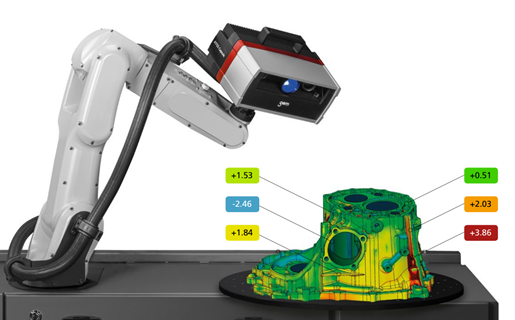
The ATOS Capsule is an optical precision measuring machine for full-field digitizing of contoured part geometries.
The fringe projection system of the ATOS series is used for production quality assurance of small to medium-sized parts and excels by its high precision for fine details. ATOS Capsule is used, for example, for first article inspection of gears, turbine blades and wheels as well as medical parts. In this use case ATOS Capsule is used for dimension analysis of machined workpieces for evaluate the whole workflow of virtual machining. This device allows to scan the real surface and evaluate dimensional and geometrical errors. The scanning device can be stable or movable using for example industrial robot, as shown in the Figure 5.
Another machine used for evaluation purposes of machined workpiece is coordinate measuring machine (CMM). This machine allows precise dimension control of the workpiece using touch probe. The CCM machine has a very precise kinematic to allow low errors in measurement.
Software Framework
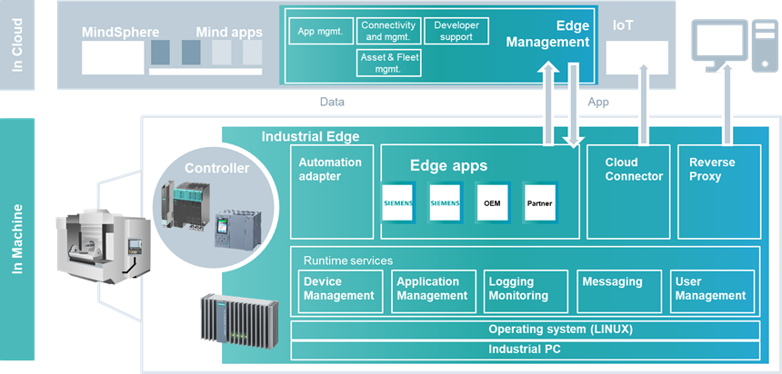
The Siemens Sinumerik Edge uses architecture described in Figure 6. There is Linux operation system running on IPC and runtime services for app management. There is also cloud connector for providing the data into cloud. Edge apps can be developed by user. Via this application the additional monitoring function can be developed for increase productivity and efficiency of machine tool.
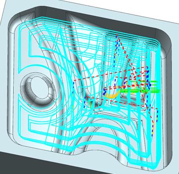
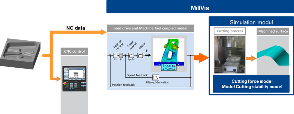
For virtual machining software Milvis is used. It is self-developed software at the Czech technical university in Prague for managing all the parts of digital twin of machine tool – CNC control system, feed drives, mechanical structure, cutting process (Figure 7). It is possible to carry out the virtual machining via Milvis. It means, that the machined surface is obtained, which can be analysed. This can help with tuning of the control system, because impact of change of each parameter can be checked using this virtual machining. It is mostly used in a case of complex surfaces, where the control system setting is fundamental for good results. After setting of all the parameters the real machine tool can use this parameters and real machining is carry out.
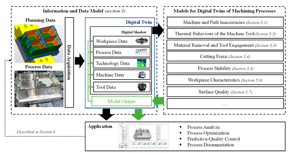
Another software for preparing of digital twin of machining process is postprocess digital twin developed at The Fraunhofer Institute for Machine Tools and Forming Technology (IWU). The architecture of the digital twin is described in Figure 8. The information model is the heart of standardized and structured data acquisition and covers both the planning data and the process data subdivide their information into five data categories (workpiece data, process data, technology data, machine tool data and tool data) which must be made available for the digital representation of the machining process terming the result “digital shadow”. The provision of these five data types only creates the prerequisite for a real-time-capable evaluation while the feedback of derived process knowledge is missing or at least not up to date. Either way, the “digital shadow” is seen as an essential part of the physical/virtual transformation in machining. For digital twins of machining processes, it is particularly important that the “digital (process) twin” not only represents the physical object—respectively the subtractive removed parts of this object—but also the machine tool, the machining process as well as the tools and their involvement and interaction in the form of process parameters. (source: IWU)
Communication Platform
For communication between software and hardware is used S7 protocol and OPC-UA protocol. S7comm (S7 Communication)[1] is a Siemens proprietary protocol that runs between programmable logic controllers (PLCs) of the Siemens S7-300/400 family. It is used for PLC programming, exchanging data between PLCs, accessing PLC data from SCADA (supervisory control and data acquisition) systems and diagnostic purposes.
[1] https://wiki.wireshark.org/S7comm
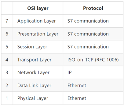
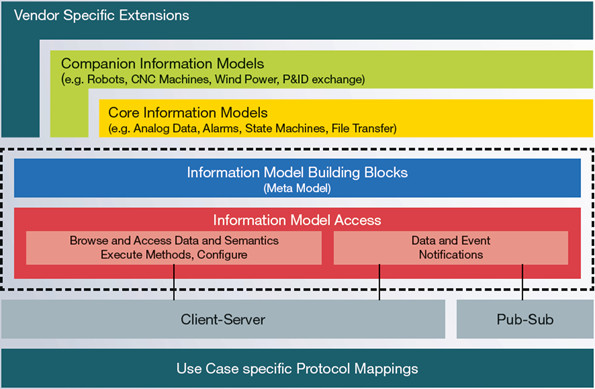
The OPC Unified Architecture (UA)[1], released in 2008, is a platform independent service-oriented architecture that integrates all the functionality of the individual OPC Classic specifications into one extensible framework. The multi-layered architecture of OPC UA provides a “future proof” framework. Innovative technologies and methodologies such as new transport protocols, security algorithms, encoding standards, or application-services can be incorporated into OPC UA while maintaining backwards compatibility for existing products. UA products built today will work with the products of tomorrow.
[1] https://opcfoundation.org/about/opc-technologies/opc-ua/
Scenario Description (Applications)
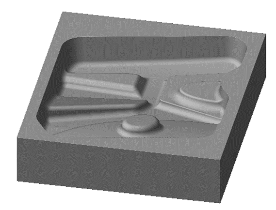
The scenario of the use case is following. The workpiece with advances surface was chosen. The workpiece is shown in Figure 11. It is a die mould used for production of metal sheet product. The goal is to machine it from the block of material using a horizontal machine tool H630 at CIIRC. For presenting a distributed production and digital twin approach the real machine tool is tuned via software Milvis. It means, that the virtual machining is carried out and the control parameters of the machine are tuned. The parameters are distributed to the machine tool via a normalized data model. Next step is a real machining. During this real machining all the process data (low frequency and high frequency) are collected using Siemens Sinumerik Edge device. After the machining the digital twin of the workpieces is built up using the recorded process data. It is possible to show the result (surface errors, geometrical errors, dimensional errors) via the digital representation of the workpiece. The goal is to show possibilities and advantages of digitalization of machining process and using a digital twin.
List of Used Modules and Realized Applications
| Module Name | Description | Application |
| Data mining | Collection of process data from machine tool control system. | Production monitoring |
| Virtual machining | Using detailed model of the machine tool including drives and control system virtual machining is carried out. | Production tuning |
| Postprocess digital twin | Recorded data from real machining is used for error analysis and production protocol for future evaluation. | Data driven production |